Thanks for your interest in my HWEF article from 2012. Even though it’s from october 2012 and it’s outdated because I’ve come to many new insights (mostly thanks to the knowledgable Mr. Owen Duffy), I think it’s still a good starting point to get some understanding about this antenna. If you’re interested in HWEF antennas, I recommend you read the more recent articles I’ve written about it:
HWEF vertical for 20/15/10 (updated October 2020)
Holiday 40/20/10 HWEF vertical V2 (2013)
Holiday 40/20/10 HWEF vertical V1 (2012)
Articles from Owen Duffy that are worth reading:
RF transformer design with ferrite cores – initial steps (Owen Duffy 2019)
WW1WW’s matching transformer for an EFHW (Owen Duffy 2018)
End fed matching – VK3IL design on LO1238 (Owen Duffy 2017)
End fed matching – PA3HHO design review #2 (Owen Duffy 2016)
End fed matching – PA3HHO design review (Owen Duffy 2015)
End fed wires – new hams love ’em (2014)
Following the original article I wrote back in 2012. Please be aware that…
- … the described antenna in this article is NOT “my design”!
- … this is just a compilation of information from Dutch forum http://www.zendamateur.com
- … the antenna design is based on a PAR EndFedz that was available back in 2012
Multiband half wave end-fed HWEF (2012)
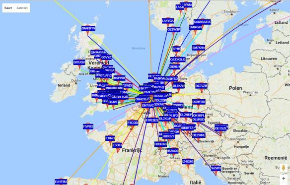
Yes it’s cheap, easy to build, doesn’t need radials and it works GREAT! It sounds to good to be true. Below the result of a 30 minute daytime session on 40m in WSPR mode with 0.6 Watt ERP using my trapped 80/40/20 HWEF. Even though the WSPR mode is very efficient and claims a gain of +30dB compared to a “normal” signal, I think the results are impressive.
Introduction
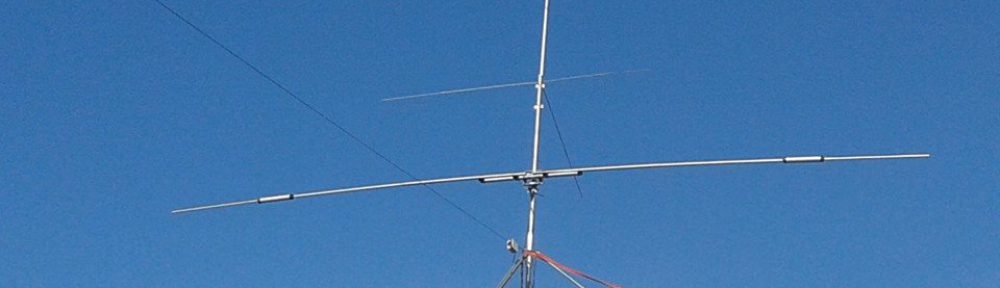
In the Netherlands, the HyEndFed antenna by PA3EKE, in principle an improved copy of the PAR end-fedz is a very popular antenna. The antenna seems effective / efficient, can be put up as a vertical, horizontally or as a sloper, is low on QRM/QRN, does not cause any RFI in the shack, is very practical to put up (feedpoint very near to your transceiver) and it’s pretty easy to build. On the (Dutch) forum www.zendamateur.com there’s a lengthy thread on how to build this antenna and many Dutch hams have succeeded in building one themselves. I use one for my holidays and from my home QTH I have put up a multiband end-fed aerial for 80/40 (which is doing OK on 20m as well ). When I’m working international stations on 80/40, many people are interested in my 80/40 antenna, therefore I made this artible with some explanation and a summary of the info I got from the forum.
How it works…
The heart of the multiband (you could as well call it “anyband”) end-fed is a 1:50 (to 1:60) impedance transformer that feeds half a wave of wire fed at the end (or beginning) where impedance is (very) high (aroun 3k Ohms). You could consider the end-fed half wave an “off center fed” dipole that’s fed VERY off center, like a Windom taken to the extreme: total length half a wave divided over one very long leg and one very short leg. The short leg is so short, that we actually leave it out. I have seen some end-feds that have about 1m of wire hanging from the transformer. Just like a windom, it doesn’t seem to require any radials.
Many people are claiming it can’t work without, but people are using this antenne everyday are kinda proving it does. In my perception, VERY well actually. I reckon it needs some ground, but not much because of the high impedance that is “Voltage fed antenna”. Many people claim the outside of the coax will function as a radial and the coax will be radiating causing RFI probems. I’ve used my 80/40 end-fed regularly with 400W with the feedpoint (litterally) 3 meters above my head and I never experienced any RFI problems. Yes it will use a (very short?) length of the coax braid as a counterpoise… so what? I’m using 10m of military grade RG58 that passes an FT-240-43 core eight times before it enters my shack. No problems with RFI whatsoever.
Signal reports I get on 40m are *very* good, comparably with and mostly better than stations that have a full size Windom or dipole for 40. I don’t want to brag, but in many local rag chewing QSO’s I often was one of the louder stations. On 80m my signal reports compare to a friend who used a 2 x 14m open line fed aerial. The end-fed for me however is way more practial because you can span it from an (attic) window and let it slope down to a tree, small mast or garden shed in your back garden. Anyway, the typical impedance at the end of half a wave is around 2500 – 3500 Ohms. The 1:50 auto transformer transforms this high impedance to much lower 50 – 70 Ohms. Once built, you can connect half a wave length for *any* band as the auto transformer just transforms 2k5 impedance to 50 Ohm impedance. Hook up 10m of wire for 20m band, 15m of wire for 30m band, 20m of wire for 40m band; what you like. The “multiband” feature of the antenna is that e.g. half a wave for 20m happens to be a full wave for 10m so the 20m half wave will be resonant as a full wave on 10m. Another trick to add a third band is to add a trap or high impedance coil at the end that “disconnects” the wire that’s after the trap/coil on high bands and acts as a loading coil on the lowest band. Here’s a drawing of the principle for the only 12m long 40/20/10 version:
My 80/40 version (2012)
My 80/40 version that I use on a daily basis, regulary with 400W PEP has a 1:60 autotransformer using two stack FT-240-43 cores. The core has three bifilair windings (= 3 primary + 3 secundary) Than 8 more secundary windings, than it crosses the stacked cores and than there’s 12 more secundary windings. The winding ratio is 3 : 23 or 1:7.7. The impedance transformation will be the squared ratio so a little less than 1:60. My first version had 21m of wire, than a 115 uH coil (1mm enamelled wire on a 50mm PVC pipe) and then only 1.5m of wire. This worked great on 40m and “acceptable” (far from great) on 80m. The bandwidth on 80m however was *very* limited: only 50 – 60 kHz. Because I could put up a little more wire, I peeled down the coil to 80 uH coil. To my surprise, only 3m of wire were sufficient to get resonance on 80m. Again, great on 40m, “reasonably well” on 80m but still limited bandwidth (only 50 – 60 kHz). From the tree that held the end, I could go down another 4m so I replaced the 80 uH core with a 40m coax trap (11 wdg of RG58 coax on a 40mm PVC pipe). After the coax trap around 12m of wire were required for resonance at 3.7 MHz. Just a little more than I could span away. With some coiling around the tree, I managed to get rid of all the wire, but not so neat solution. The bandwidth was now 200 kHz so from 3.6 – 3.8 I was able to operate it without tuner (SWR better than 1:1.5). Total length around 33. Because the resonance dip on 40m was a bit high at 7.15 MHz, I added a length of 30 cm of wire before the coax trap just hanging off the trap. This is a great trick to fine tune resonance if you’re 40m half wave wire is a little too short. Latest version of this antenne has a home brew L/C trap made of a 7 uH coil (on 50mm PVC pipe) combined with a 15 kV 68 pF door knob capacitor. After the trap, there’s now around 11m of wire. I used 8m and than some end loading with 2 wires in a V-shape. Ends of the V-shape are at 2m AGL (safe height for my kids). Bandwidth is now around 150 kHz on 80m.
The “original” (PAR / HyEndFed) 40/20/10 version
This antenna is a 12m long multiband antenna for 40m, 20m and 10m. It has a 1:60 autotransformer with a single FT-140-43 core for 100W PEP or a bigger FT-240 for 400W PEP or 100W CW/RTTY. The transformer has two bifilar windings (= 2 primary + 2 secundary), 5 or 6 more secundary windings, than wire crosses the core and than 7 or 8 more secundary windings. The winding ratio should be between 2:14 (1:7) and 2:16 (1:8) for a 1:50 – 1:64 impedance transformation. My experience is that you need 1:60 to get the impedance of the highest band around 60 Ohms. After the transformer there’s around 10.2m of wire, then there’s a 34 uH coil and abt 2 more meters of wire. This antenne will work as a full wave on 10m. You will need to solder a 150 pF capacitor on the INPUT of the transformer to get the SWR down on 10m. On 20m the antenna will be a full half wave. On 40m the antenna electrically acts as half a wave but physically is dramatically shortened. Bandwidth on 40m is limited to 50 / 70 kHz. If you need more bandwidth and can put out a little more wire, replace the 30 – 40 uH coil with a 20m coax trap or normal L/C trap. Depending on the inductance of the trap, you will need 5 – 6 meters of wire after the trap, total legth 16m. With this version, bandwidth on 40m will then be around 150 – 200 kHz. If you want to go the full monty, just hook up 20.4 meters of wire and you will have excellent effiency and full bandwidth on 40m and some gain on 20 and 10. For a 30/15 meter version, just hook up 15+ meter of wire. For a 80 – 10 version, make an autotransformer like my 80/40 version (with 3 bifilar turns on an FT-240-43) and hook up 20+ meters of wire, a 70 uH coil and 2.to 3 meters of wire (or 40+ meters if you have enough space).
My 2012 holiday version 40/20/10 (only 7.2m long)
My holiday version is very similar to the normal 40/20/10 version but has two coils instead of one. First there’s around 4,8m of wire, then a 15 uH coil (to trap 10m frequencies), then around 1.2m of wire, then a 34 uH trap and another 120cm of wire. This antenna works great on 10m, very well on 20 and of course relatively poor on 40m. When conditions were up I worked whole of Europe from a camping site in France. When conditions are average, performance on 40m is defenitely a compromise obviously.
How to make the “magic box” (1:50 to 1:60 autotransformer)
The “magic box” holds an HF autotransformer (UNUN) that transforms 3000 Ohm to 50 Ohms. The primary : secundary winding ratio is 1:7 or 1:8. For 100W, an Amidon FT-140-43 core will do but for 100+ Watt SSB or long CW or digital mode QSO’s you’re better off with the larger FT-240-43 core. At www.kitsandparts.com (“the toroid king”) the FT-140-43 sells for $5 per 2 pieces and the FT-240-43 sells for $8 a piece. I’m using two stacked FT-240-43 cores for my 80/40 version which easily handles 400+ Watts, probably more. I reckon a single FT-240-43 can handle 250 Watts easily.
On the core, you wind two “bifilar” turns (wires need to be twisted), then 14 more single turns. The primary side of the transformer has 2 windings (one wire of the 2 bifilair windings) and the secundary side of the transformer has 2 (other bifilair wire) + 14 (normal) = 16 windings. The ratio of the windings is 1:8 so the secundary Voltage will 8x the primary AND the secundary current will be 1/8 of the primary. Therefore, the impedance will be transformed in a 1 : 8 x 8 = 1:64 ratio. That’s what we want to match 3kOhm to 50 Ohm right? The original auto transformer has a 1:7 winding ratio (2 bifilar windings + 12 extra secundary windings) which results in a 1:49 impedance transformance. My experience is dat 1:49 results in slightly too high impedance so that’s why I opted for 2 more secondary windings. In practice you will find that on 10m the impedance is too high, on 20m it’s spot on and on 40m it’s too low so you need to find a compromise to be able to work three bands with one transformer. Bear in mind that the bandwidth of the auto transformer is not unlimited, a transformer wound on an FT-140-43 will work well on 10 and 20 and reasonably on 40, a transformer wound on FT-240-43 will work reasonably on 10, very well on 20 and pretty good on 40. If you want to use it for lower bands (merely 40 + 80 or even 160) you need MORE inductance (bigger or multiple cores).
Note that this transformer is different to a 1:9 UNUN that’s popular for random length end-fed antennas. The 1:9 transformer transforms 450 Ohms to 50 Ohms so you could use it to feed a non-resonant (random) wire length (impedance typically between 200 and 600 Ohms). The 1:9 UNUN defenitely needs a counterpoise because it is not a resonant half wave and it needs a reference to ground to radiate properly. The performance of the end-fed is much better than an end fed wire with 1:9 UNUN. On Youtube there’s a nice comparison video (in Dutch, but the pictures paint a thousand words): http://youtu.be/Ybbv_h1HFw0.
Here’s the schematic of the 1:60 autotransformer:
Use 1mm enamelled wire. Twist a length of abt 6 – 8 inch of wire with a length of 40 inch of wire. It is good practice to tape the FT-240-43 core with (e.g. PVC or teflon) isolation (tape). Start winding (back) at point B. This is the point where the bifilair winding ends. Make two windings back. Solder the beginning of the two bifilair windings together. Later, this will be connected to the ground of the SO393 female jack (or BNC if you like). The end of the bililair winding will be the “hot” input; the center of the female jack chassis. Cut exces wire, leave about 1½ inch for soldering. Now from point B (where you started winding back) continue winding the single (long) wire forward and make 7 single windings. Then let the wire go THROUGH the core to the other side and make 7 more normal windings. Cut exces wire (leave 1½ extra for soldering). This end, will be the feedpoint of the wire.
On the INPUT, solder a 150 pF ceramic disc capacitor, preferably 500V or better. This cap “shortens” the antenna for 10m to compensate for the impedance of a full wave (slightly different for a full wave). I used a blue 3 kV cap, they’re available from many electronic shops.
Following some pictures taken from www.zendamateurforum.com (ham radio forum in Dutch) how the transformer should look like.
PA1RIK 40/20/10 version:
PG3N 40/20/10 version:
Close up of PA3GWO’s autotransformer:
Close up of PA3GWO’s loading coil (high impedance trap for 10/20m)
Here’s the transformer of my (PA3HHO) holiday version (only 7m long). I left out the 150 pF cap because my holiday version had TWO coils; one 15 uH coil at 4,8m and one 34 uH at 6m. If you understood the principle; you understand my holiday version is a half wave for 10m as well because the small coil also “disconnects” the wire + coil + wire that’s behind it on 10m.
This is the coil that I made for my first holiday version that was only meant for 20/10. It had the above transformer, then 4.8m of wire, then this coil (I think I recall removing some windings), then 1.2m of wire.
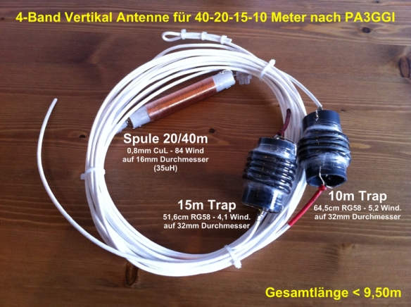
PA3GGI 4-band version (only 9,8m long) by DL4ABB:
How to tune?
First tune the band on highest “half wave band”. For the 40/20/10 version this is 20m (on 10m it is a full wave!!). You can tune by varying the length of the 10m wire between the transformer and the trap. You probably need less than 10m, this is normal, it’s a little less than a ½ wave because of the velocity factor of the wire you use. If SWR is best high in the band, you might need to add a little more length. If SWR is best low in the band, you might need to make it a little shorter. A good tool for tuning is an antenna analyser (I use a RigExpert AA-54; can’t live without it!), maybe you can borrow one from a friend. If 14.2 MHz is OK, the SWR on 28.5 should be OK as well. If not, you might want to “play” with different value capacitors, anywhere between 100 and 200 pF. My experience is that 150 pF seems just right. If the highest bands are OK, tune the shorter wire after the first trap or coil to tune the next half wave band (40m) and so on. Use an isolator at the end and fold some of the wire back (using tie wraps) this is an easy way to make it shorter or longer. The wire that’s fold back is more or less “almost invisible” electrically (not totally, but it works). If you have too much wire and SWR is optimal low in the band, just cut 3” and start tuning. The tuning might be different when erected to a fishing pole (use fiberglass poles only, NOT the ones with carbon!!) compared to put away horizontally or as a sloper, not much though.
Here’s a nice Youtube video of a Dutch novice (PD prefix) station working Canada with only 25 Watts using an end-fed. He almost burst into tears (He keeps repeating “I can’t believe it”)… What a nice hobby! http://youtu.be/F7kbBDftRRc
All pictures I used are “borrowed” from from the Dutch forum www.zendamateur.com, if you’re interested take a look at the (pictures in) the whole thread: http://www.zendamateur.com/viewtopic.php?f=5&t=6682. Some browsers can translate pages using Google Translate. There’s many pages in this thread with many more nice pictures. One guy even made a “mobile version” on his car, 12m long, can you believe it?!
If you have any questions, just let me know (leave a reply on this blog or send me an email, info is on QRZ.com).

Hallo Pleun, bedankt voor je beschrijving. Denk dat veel amateurs hier wel naar opzoek zijn. Het forum onderwerp is leuk, maar verwarrend. De 1 heeft het zo de ander weer anders. Vind het maken van de autotrafo nog al ingewikkeld er uit zien. Als je het een paar keer gedaan hebt zal het wel meevallen denk ik. 73, Bas
This is a neat article, and was very imformative. I’m new to antennas, but have a specific project where an end-fed antenna would make my project much easier, both due to weight and ease of installation. However, I’m running at 151MHz, so I thought I would ask if anything needs to be different. Would I still build the autotransformer the same way? Since I’m working on a receive-only antenna, could I use a more compact toroid?
Also, this is radiating like a dipole, right? So could I match it up with a second wire like in http://www.qsl.net/dk7zb/2m-port-SSB/2-Element.htm, in order to make a somewhat directional antenna?
The end fed is not suitable for VHF frequencies, but you can tune a half wave whip to 50 Ohms using a coil and capacitor. There’s many info in the internet, Google is your friend HI.
Too bad it won’t work at those frequencies. Thanks for the great article, though.
>
In some cases you use 2 turns on the primary and in other cases 3. Is that just to get the primary-to-secondary ratio you wanted or is there some other reason for choosing 2 versus 3 turns on the primary?
Hi Kevin. The typical impedance of a half wave is around 2k5 – 3k Ohm so we need impedance transformation of 1:50 – 1:60. The impedance transformation ratio of an auto transformer is determined by the winding ratio. Actually, it’s the winding ratio squared. We need a 1:7 to 1:8 ratio to get 1:49 (with 1:7 winding ratio) or 1:64 (with 1:8 winding ratio) impedance transformation. Regardless of the winding ratio, there’s another important factor for the auto transformer to work efficiently and that is the primary inductance which is dependent on the frequency you want to use. Lower frequencies typically like to see higher primary inductance. There’s two way to acomplish that: bigger or more (stacked) cores or more primary (thus secundary, you want the ratio to stay the same!) windings.
Two primary (bilfilar) windings on the smaller FT-140-43 core would be OK for 40 – 10 meters. If you want the auto transformer to work on lower frequencies (80m_, you need a little more inductance. I know that the commercial HyEndFed antennes by PA3EKE use the same number of windings (2:14) but use the bigger FT-240-43 core. The FT-140-43 has an AL-factor of 885, the FT-240-43 has an AL factor of AL1075. That higher AL factor obviously is sufficient to cover 80m (read on).
Based on the above, you could say that an auto transformer is not a “broad band” device. I.o.w. it doesn’t cover 0 – 100 MHz, it has a certain “working range”. Typically 2:14 (or 2:15 or 2:16) seems to work for 80m – 10m. Best performance is in 40 – 20 meter band. On the lower and higher band, the transformer is a little less efficient. I designed my end-fed specifically for 80 and 40 meters AND for high power. It would probably be to just stack two FT-240-43 but I didn’t want to take any chances so I also added an extra primary winding. So the answer to your question is that I use 3 primary windings if I want the auto transformer to perform well on lower bands (80/40). I used two cores so it would be possible to use more power (400W is legal limit over here). I later realised it might be a little overdone to have two cores AND and extra winding, but in practice my end fed works PERFECT on 80m and 40m with 400W PEP so I just leave it like that. I hope this helps!
Be aware of the fact that the auto transformer is not a broadband has a certain frequency range
For a certain frequency, you need
The number of windings you use
As stated before: the info on zendamateur.com is confusing. This page exlains clearly how the end fed works and how to build it.
I have all the parts in my posession and will build one soon, by the use of the info on this page.
Thanks for the effort to make it. Exactly what I was looking for!
73 Martin PA2RUS
Graag gedaan Martin en succes met de knutselarij. Mocht je nog vragen hebben, dan hoor ik het wel. Een analyser is wel makkelijk bij het afregelen, misschien heb je er zelf een of kun je ‘m van iemand lenen. 73 de PA3HHO
The use of small diameter coil is required to reduce the Q of the coil ???
Not sure but I think that’s the idea yes; reduced Q gives more bandwidth but also limited efficiency. I have never used those small diameter coils though, I used 40mm and 50mm PVC pipes (grey) on my end-feds. On my 80/40 QRO end-fed I’m currently using a 50mm coil combined with 68 pF doorknob capacitor tuned for resonance at 7.5 Mhz. On 80m I have now much less “loading” so I have around 120 kHz bandwidth on 80m (SWR better than 1:1.5) and 200 kHz bandwidth with SWR better than 1:2. It actually works very well on 80m and excellent (like a full-size dipole) on 40m.
End feeding can not make antenna work better , nor worse. Off-centre feeding does not change antenna current distribution, therefore radiation pattern remains the same. End feeding offers mechanical advantages, heavy bits (coax and balun) can remain at the bottom of the antenna. Therefore you can use simpler antenna mast, say fibreglass rod instead of tower.
Wideband transformers using ferrite toroids are much better suited to lower impedance ranges, say 1 to 300 ohm – not to 2400 ohm.
Excellent info! Every detail I need to know is perfectly well described in this page. Thanks a lot, Pleun!
Pingback: Another balun question... this one for HF - The RadioReference.com Forums
I made this antenna 40-20-10 with a FT-240-43 core and after tuned the antenna
I tried with a 200-2 red core with same turns but the ros was very hight.
where I’m wrong ????
tks
i0kib
FT240-43 is a ferrite core with Al value of 1075 whilst the T-200-2 is a totally different iron powder core with Al value of 12. The two bifilar turns (primary side of the transformer) on the FT240-43 has an inductance of 4.3 uH, on a T-200-2 core the inductance is way too low, only 0.05 uH!! Also optimum range for T-200-2 is 250 kHz – 10 MHz, for the FT240-43 it’s 5 – 400 MHz for wideband transformers and .5 – 30 MHz for power transformers. In other words, do not use the T200-2 for this. Check the specs: http://toroids.info/FT240-43.php and http://toroids.info/FT240-43.php
They’re totally different.
Using #2 iron powder material, it is possible to make end fed tuner. You can make tuned circuit autotransformer, and coil Q will be over 300 for frequencies under 2 MHz. At higher frequencies it is better to use air cored inductor.
Pingback: Hi End Feed Antenne | ANTON's FUNKPERLEN
I want to build a multiband end fed 80/40/20/10 (15)
I planned to use FT240-43 core , 2 bfilair windings primary and 14 secondary ( 23 meters wire) and a 110uH coil for 80 meters. What would be the right capacitor value on the input. Will 100pF do ?
Hallo Wilfred, you kunt gewoon Dutch talken to me hoor. Dat Engelstalige was even een tijdelijke overweging voor mijn internationale publiek maar ik vind het toch prettiger om in het Nederlands te schrijven en bovendien translate.google.com is your friend HI. Het korte antwoord op jouw vraag is: “ik weet het niet, maar wat jij wilt, kan volgens mij zowieso niet!”. Volgende PD7MAA kan het wel, zie zijn blog: http://pa-11019.blogspot.nl/2012/04/149-transformer-for-endfed-antennas-35.html
Je kunt het altijd proberen natuurlijk, maar de trafo die je beschrijft met een 2:(2+14) = 1:8 ratio geeft weliswaar een impedantietransformatie van 1:64, echter die 2 primaire wikkelingen hebben te weinig inductie om een 80m signaal lekker te koppelen, sterker nog, dat is al aan de krappe kant voor 40m. Om 40m lekker te koppelen heb je eigenlijk al drie windingen nodig, moet het trafo ook nog voor 80m werken, dan zeker drie wdg en dan nog het liefst op twee FT-240-43 kernen. Zo is de trafo van mijn 80/40 end-fed, dan 20+ meter draad, dan een L/C trap met 10 kV 68 pF doorknob condensator en een 7 uH spoel, dan nog +/- 11m draad. Dat werkt als een speer.
Ik zou er gewoon 20m draad aan hangen met de bekende 100 – 150 pF in het doosje voor betere match op 10m. Ik had dat afgelopen week ook zo toen ik een paar dagen bij PE0F /P op zijn “privé camping” stond. Die 20m draad is ook nog eens een kwart golf voor 80m, heeft daar dus lage impedantie en daar de 1:50 trafo (die daar niet erg efficient is) gaat dat nog eens naar beneden. Tot mijn stomme verbazing kon het Z817 tunertje daar gewoon 50 Ohm van maken (hing 10m RG58 coax aan, misschien deed dat ook nog wat) en kon ik prima luisteren én zenden op 80m. Ik gebruikte 20W en was ‘s-avonds prima te horen in o.a. Nederland, Duitsland en Engeland.
Wil je lekker op 80 en 40 uitkomen, dan zou ik een 3:(3+19) = 3:22 verhouding gebruiken, zoals gezegd het liefst op 2 kernen. 20m lukt dan nog wel, 10m kun je vergeten met die trafo, inducatie primair is dan juist weer te hoog. Bandbreedte van trafo loopt echt niet van 3.5 – 30 MHz. Oja RX zal wel werken, maar TX dat wordt niet wat vrees ik maar zoals gezegd, probeer het gewoon!
Very nice info! What would be the length of a 10/15 meter version? Like a small version of your holiday version. Use a 1:64 transformator than ?m of wire, coil ?mikroHenry and ?m wire? How’s the calculation done, could you give me any hint. I’m new to antenna building but would like to learn as much as I can.
Hi Tim, a 10/15m versie would be half a wavelength for 10m (so 150/28.5) is around 5.3m, then the same coil I use so somewhere around 17 uH and then problably 1m of wire. There’s no scientific calculation behind this I’m afraid. The 40/20/10 multiband endfed uses a 34 uH coil. This coil has a high impedance on 20m so disconnects the wire that’s behind the coil for 20m signals and higher frequencies. While, in theory, it’s all linear, you can reason half the inductance (around 17 uH) will have high enough impedance to block 10m frequencies. You need to experiment a little with the wire length, thinner/thicker wire will require different lengths. Good luck and have fun experimenting!
Thank’s a lot for your help! “The coil has a high impedance on 20m and disconnects…” i get this, but it also acts as a loading coil for the lower freq? in my case for 15m meter. So there is now way to calculate this?
OK then, one basic (maybe stupid) question. Let’s say i want an end fed half wave for 40 meters (monoband). So half wave would be around 20m. Now i want do calculate a loading coil to bring the wire length down to 10 meters (may not be effective, i’m aware of this). I know how to do this for a center fed dipole but not idea how to do this for a end fed 1/2 wave.
thanks again for helping me, all the best, Tim
dipole calc.:
http://www.k7mem.com/Electronic_Notebook/antennas/shortant.html
I understand what you’re asking but I’m afraid I do not have the answer. Please note that I’m not an antenne expert, I just like to experiment with ‘m HI. You are right saying that on lower frequencies, the coil acts as a loading coil. There is however something strange that I haven’t been able to get my fingers behind yet. The 17 uH coil would still show a pretty high impedance on 15m and as well, so how on is it possible it allows 21 MHz signals? I’ve been thinking about that and discussing it with my Elmer for a long time. While the end wire (after the coil) is a capacity as well, we think (not sure though) the coil + end wire are a series resonant circuit resonating at the frequency you want the coil to pass through. It’s just guessing and doesn’t explain why it also works using two coils. Back to your question; I understand the theoretical hunger, but in practice, why would you want to build an antenne with a loading coil that’s only resonant on one frequency if you could make it resonant on two frequency at (almost) the same length. E.g. 10m length for 40m band? I would go for the 10m of wire (half wave on 20m), the 34 uH coil and 2m of wire. If it’s too long, just coil up some of the 10m wire before the coil or use some linear loading. If you can span more wire, replace the coil with a true L/C trap with less inductance and more capacity. This will give you more bandwidth and efficiency. So in the 40/20/10 version, you could replace the 34 uH coil by a L/C trap with e.g. 20 pF and 6.5 uH. It’s just guess work but I think you will need around 4 – 6 meter of wire behind the trap. First use some scrap wires that you cut to length, then use the “real” wire and add 1m and cut to length. I know it doesn’t sound very scientific, but that’s how I do it. Note that a 20m L/C trap will only show high impedance on 20m, so you probably loose 10m. My 80/40 endfed has 21m of wire, a 40m L/C trap (68 pF with 7 uH) and 13 more meters of wire. Coincidently (I think), it is resonant a little under 14 MHz so SWR on 20m is reasonably OK and tunable. That’s just dumb luck I think. The wire is slightly longer than I hoped for, so I’m thinking of replacing the trap with a version that has a little higher inductance (e.g. 10 uH) and a little less capacity (around 50 pF). I’m not sure how to calculate what the effect will be, my guess is that it will require 2 – 3 meters less “end wire” but that’s just a guestimate. I also wanted to test the trap with low Q coil (long, small diameter) and high Q coil (short, bigger diamter) to see if that makes much difference in bandwidth. Bandwidth on 40m is EXCELLENT on 80m it’s only 150 kHz for SWR better than 1:2. Maybe some toploading on the endwire would improve bandwidth as well.
Ok thanks again, you are very helpful. Why 10/15 is simple, my licens only allows 10/15/80/160 and of course VFH/UHF.
But your answer helps me a lot and of course your are right in a real world scenario its always about experimenting ; )
All the best, Tim
OK Tim, Ich verstehe. I would go for a turn ratio in between 1:7 and 1:8 making an impedance transformation ratio in between 1:49 and 1:64. If you can span the length, forget about the coil and use a decent trap. Use +/- 5.3m of wire, then an L/C trap with relatively LOW inductance for optimal bandwidth and effeciency on 15m, e.g. around 15 pF (3 kV door knob type OR a 15cm length of RG58 coax) and a 4 uH coil, that’s around 17 turns of 1mm wire around a 20mm PVC water pipe. A half wave for 15m would be around 7.5. My guess is that you need around 1.5m wire after the LC trap. Total length will be around 6.5 meter. Feedpoint as high as possible (attic window? chimney?) then span it diagonally down to garden or fence. It really works well. For 10m / 15m you will only need an FT-140-43, no need for the bigger (more expensive) FT-240-43.
Vielen Dank, I’m going to try the lc trap version, sounds better and I already thought of this in the first place. Since this will be a portable (SOTA-) antenna i’ve got a 10 meter telescopic pole that I will use . I’ll let you know how it worked out!
Die besten Grüße aus Deutschland, Tim
Hello,
I’m building PD7MAA’s 80-10m version of this EFHW antenna: http://pa-11019.blogspot.nl/2012/04/149-transformer-for-endfed-antennas-35.html
Transformer will be wound on FT-140-43 toroid.
This is approximately how it will be installed: https://i.imgur.com/bxhFXRg.png
Real life view (approximately, again): https://i.imgur.com/h2eL6Qp.jpg
Notice that the wire makes a 90 degree turn. How would that impact the antenna? Would it sill work fine? That’s the only way I can install this antenna…
The FT140-43 will give you too less inducatance for 80m. You need at least an FT240-43 and even with that toroid it is still a compromise. The bandwidth of an auto transformer is not unlimited you know. My 80/40 endfed has 3:20 turn ratio (so three primary turns!) on two stacked FT240-43 cores. That works well on 80 and 40. Even though in practice two primary turns on a single FT240-43 will work, I do not recommend this if you like the low bands (use 3 : 19 or 20 or 21 turn ratio). The angle is fine, it will affect your radiation pattern of course.
I had the idea to feed the 22,74m (no space for full 40m halfewave) from pd7maa 80/40/20/15/10’s version with his endfed monoband tuner.(http://pa-11019.blogspot.de/2011/06/20m-endfed-halfwave-antenna.html). I know this will be monoband but it will work out i think?
I calculated 13 windings on a FT-140-43 (tap at 2-3) and about 16 cm coax.
100watt max.
Not sure what you mean Tim. You state that you want to feed 22.74m of wire because you don’t have space for a 40m halfwave, but 21m of wire actually IS half a wavelength on 40m. So, what is it you want to achieve? How much wire can you span away and what bands would you like? You can make a 12m long multiband for 40/20/10. When you leave out the coil + extra wire, it becomes a 10m long dual band for 20/10. If you can span a little more, I would recommend using a true L/C trap for 10m with a lower L:C ratio (less inductance, more capicity), then add say 4 – 5 meters of wire for a very efficient 10/20 version. Tell me what you want. If you can span 22.74 of wire, you can make a full size 40/20/10 endfed.
Hoi Pleun, als eerste wil ik je even bedanken voor dit leuke en overzichtelijke artikel!
Ik heb eind februari vorig jaar een 3 bands HyEndFed gekocht. Dit is de variant die voor 40 meter elektrisch langer is gemaakt, iets wat voor in mijn tuin handig uitkomt. Nu ik vaker de HyEndFed het veld in meeneem, is het plan om een tweede draad te maken die geen verkortingsspoel en trap heeft. Nu las ik dat 20,4 meter draad zelfs nog een beetje gain zou opleveren op de 20 en 10 meter banden.
Zijn er problemen met een stuk draad van van 40 meter voor de 40/20/10 meter banden? Een eindgevoede full-wave voor 40 meter, tweemaal op 20m, en viermaal op 10 meter? Wat voor effecten gaan er dan allemaal spelen? Kan ik dan ook meteen 80 meter draad nemen, etc, etc.
Dutycycle HyEndFed?
Je geeft aan dat voor de 40/20/10 een enkele “FT-140-43” voor de 100W en een “FT-240” bij de 400W versie wordt gebruikt. Ik heb hier de 200W versie. Gebruiken die ook de FT-240(-43?) kernen? Ik lees dat er tussen 20% en 40% duty cycle (hoeveelheid processing etc) word genomen voor enkelzijband spraak. Kan ik zeggen dat er met de 200 watt variant continue (100% duty cycle modi) 80 watt gemaakt kan worden zonder problemen?
80 meter band met een 40/20/10 HyEndFed 😛
Voor jou zelfgemaakte 80 en 40 meter band antenne gebruik jij twee FT-240-43 ferrietkernen. Als mijn 200 watt 40/20/10 HyEndFed één FT-240-43 zou bevatten, hoeveel vermogen zou ‘ie zonder problemen aankunnen?
Een enorm verhaal, maar iets stukmaken omdat ik wat dom doe kost meer tijd 🙂
Met vriendelijke groet, Jeroen PD1ODE
Hallo Jeroen, bedankt voor de complimenten en je leuke reactie. De vraag waar jij mee zit, zit ik ook wel mee. Het “stapelen” van halve golven heeft sowieso invloed op de impedantie. Je kunt niet ongestraft 400m draad aan je aanpassing hangen. Een hele golf heeft aan het eind een andere impedantie dan een halve golf. Dat is ook dat reden dat er in de aanpassing van de 10/20/40 versie, een C-tje aan de primaire kant zit. Dat is om de impedantie voor 10 meter (hele golf) wat beter te krijgen. De spoel in jouw versie, werkt als “trap” voor 20m en 10m, je hebt dus electrisch een hele golf voor 10m een halve golf voor 20m en een electrisch verlengde halve golf voor 40. Waarom het dan met 20,4 meter draad opeens wel goed gaat op 20m is mij eerlijk gezegd ook een raadsel. Dan zit je nog met faseverschillen, volgens mij heeft het alleen zin om halve golven te stapelen die IN FASE zijn. Je zult dus tussen twee halve golven een derde niet stralende halve golf nodig hebben, volgens mij doet men dat bij draadantennes met een (al dan niet opgerolde) lus bestaande uit twee kwart golflengtes. De endfed die jij hebt, heb ik ook gemaakt en gebruikt en het viel mij op dat die, zelfs bij condities, niet geweldig presteerde op 10m. Ik begeef mij op glad ijs, maar ik heb het gevoel dat dat komt omdat het twee halve golven zijn die UIT FASE zijn. Bij antennes die langer zijn dan een halve golflengte, komt dat er als complexe factor bij. Ik heb zelf het idee, dat je met een even veelvoud van halve golven géén extra gain krijgt, in tegendeel; de halve golven staan in tegenfase dus afstraling “dooft” zichzelf voor een (groot?) deel uit? In de buurt van de antenne niet natuurlijk, maar op een afstand wel? Geen idee… dat is voor de echte specialisten. Bij een oneven veelvoud heb je evenveel gain als bij een enkele halve golf. Ik beperkt me dus tot halve golven. Omdat mijn 80/40 endfed net een tikkeltje te lang is, overweeg ik om deze uit te breiden met een 20m trap met weinig inductie (dus nauwelijks electrisch verlengend) en een vertikale versie voor 10/15. Hoe je het ook wendt of keert; het stralingsdiagram van dat soort lange antennes ziet er vaak vreemd en grillig uit. M.b.t. power: ik gebruik mijn 80/40 endfed met 400W LSB en dat geeft, zelfs bij langere tijd intensief zenden (PACC!) geen probleem. Ik denk dus dat je kunt zeggen dat de FT240-43 wel 200W SSB aan moet kunnen. Of het verstandig is om daar 80W CW of digimode in te stoppen dat weet ik niet, maar waarom zou je? Als ze je met 25W niet kunnen nemen, dan gaat dat met 80W ook zeker niet. Al jouw vragen zijn naar ik aanneem ook puur hypothetisch want met de N-registratie mag je maximaal maar 25W maken toch? Of heb ik weer iets gemist?
Hi,
Does the length of the coax matter for this kind of antenna? Does the rule of 1/2 wave * 0.66 for RG58 coax apply here?
There’s no required coax length, in other words, the feedline is NOT part of the antenne system. The antenne might need just a tiny bit of counterpoise from the coax so if you’re considering a RF choke (11 turns of RG58 on two (stacked) FT240-52 toroids make a GREAT wide band choke), position it 2 – 3 meters below the feeding point (1:50 transformer).
OK, thank you. I currently use 8 turns of RG58 on FT240-43 about 1m from transceiver. This is what you described earlier. I do not experience any RFI problems yet. Have you noticed any difference between putting choke near the feed point vs near the transceiver?
Welcome.
I have made 3:23 ratio transformer with 150pF/3kV capacitor. I’m using ~20 meters of 4mm^2 wire (for 40m band) and i want to add coil or trap and next ~10 meters of wire to coverage 80m band with best possible swr.
I know that in examples above 115uH coil was used with 1,5m extra wire. Then 80uH coil with 3m extra wire for better bandwith on 80m. Another example is 7MHz trap from RG58 coax. Last one is homebrew trap using 7uH coil with 68pF 10-15kV capacitor.
I understand all these examples but I want to know how to calculate coil for wanted lenght of wire. I have ~20m of wire and ~30m of avaible space to use for antenna. How to calculate coil with expected ~10m of extra wire next to coil. Or generaly how to calculate coils and extra wires for end fed antennas.
Next question is what is an advantage for using coil or 7MH trap to extend 20m+ wire for 80m band. What are the diferrences in using coil and using trap?
Jakub SQ9PDJ
Hi Jakub,
To be honest, I have the exact same question. I don’t know how to calculate this. If you only want to use a coil (that acts as an RF choke for higher frequencies), you cannot go any lower than 70 uH in order to choke the 7 MHz signals. I guess it needs around 3 – 4 meters of wire after this choke for resonance on 80m. My version was just a little too long for my back yard but instead of changing the 40m trap (increase the inductance), I decided to add a 20m trap as well that I wound on a Fritzel isolater. I think (not sure) it’s 6 uH with 20 or 30 pF (ceramic door knobs). So now its (ballpark figures): transformer – 10m of wire – 20m trap – little less than 7m of wire – 40m trap – 11m of wire. Again, I don’t have exact numbers because I used the RigExpert AA-54 to analyse the antenne and cut the wires to length and did not measure the lengths afterwards. My original version had 11 – 12 meters of wire after the 40m trap, my guess is that if you want less wire, you need around 10 – 15 uH for the L. An antenna elmer once told me that the length you want to fysically shorten the antenne with, needs to be +/- on the coil. Just experiment with some coils and you’ll find out. That’s the way I did it!
Hello!
I want to build the 80-10m version of this antenna, but did I understand it right, that the inductance of the coil is not very critical but should have a min 70uH???? You find a lot of antennas with a build in coil of 110uH.
So my antenna should work with the 85uH coil that I already have here?????
The antenna will not be very high (abt. 9m above ground), should I use a 1:49 or 1:64 transformer???
73s
The inductance is not critical but obviously it has a direct impact on the length of wire that’s behind the coil. 70 uH is enough to “choke” 40m signals so you should be fine with 85 uH. The length of wire after the choke will be a little longer, my guestimate is around 2.5 – 3.5 meters. The transformer is a compromise because you will notice that on 10m the impedance will be a bit under 50 Ohms and on the lower frequencies the impedance will be a bit over 50 Ohms. If 80 and 40 meters are your main bands, I would go for an extra secundary winding (or two), if 20m is your main band, stick to the 1:49 ratio. An antenna analyser is a great tool to measure impedance, if the impedance is too high (over 50 Ohms) on your favorite bands, you might want to consider one or two extra secundary windings on the auto transformer.
Very useful informations indeed.
I will use a 20m long wire without a load coil, as I read it should work on 40, 20,10m and also 15m, but with tuner. How should I build the transformer (any special observations in this case?) ?
And would I be able to use it (with tuner) also on 80m (I don’t need high performance on that band)?
Hi Conrad, thanks for the comments. For a 40-10 version I would use a single FT240-43 toroid with 2 bifilar (primary+secundary) turns, then another 5 turns on the same side, then cross the toroid (go through it) for another 7-8 secundary turns. The 2:14 (or 2:15) ratio will make a 1:49 (or 1:56) impedance transformation. If you’re planning on using it for 10m, you will need a 120 pF ceramic cap on the INPUT (the 50 Ohm side) to compensate for the double wavelength on 10m. You will probably NOT be able to use it on 80m because 20m of wire is a 1/4 wavelength for 80m and has low impedance. The transformer will transform it to a VERY low impedance which, even for a good tuner, is very tricky to compensate. Instead of that, you could add a 85 – 120 uH coil at the end and 1.5 – 2.5 meters of wire. Electronically this will make half a wave on 80m. Please bear in mind that the efficiency is relatively low on 80m and bandwidth will be very small (but tunable on full 80m band). Goodluck!
How about appr. 40 m of wire with no coils, should work also on 80 mb. I could try this in my summer qth where space restrictions do not apply !
73 de Heikki (OH2LZI)
Correct… that should work very well!
Thank you for this article! I made a 80 40 version using a ft240 43 with two twisted wraps followed by seven then crossed through and seven more using 14 awg magnet wire. Then ran 126 feet of 14 awg copper stranded wire. I’m very new to ham radio with zero prior experience in electronics. So needless to say I’ve been quite overwhelmed trying to take all this in.
I don’t have access to an analyzer so I don’t know if any of it is right. My swr are good on 80 a little low in the band and 2:1 on 40. Which is fine for the Kenwood internal tuner. I’ve been able to tune all of both 80 and 40. I have 32 feet of rg8x up from the shack feed point of antenna is 20 feet off the ground. It then goes across my house 55 feet to a pole that’s 25 feet high so slightly upwards. Then cuts 90° to the left and goes down to the 6 foot tall wood fence at the back of my small city lot. There’s also power lines running behind my house Right at the end of the antenna that I think are the cause of the high (s7) noise floor.
This is probably a stupid question but can I build a coil/trap with out an analyzer to shorten the antenna to get get it further away from the powerlines? Is there some basic math or online calculator to figure out how much wire and at what diameter to wrap it? I have 14 awg magnet wire. I have asked the locals I know and sadly they suggest buying expensive antenna systems instead of building affordable (reasonable!) Antennas. So I’m left to figure this out…. thanks for your help and from posting this article!
73s from west texas! And hope to meet you on the air!
-Micah
W0abh
Hi to all,I want to build a 10/15/20. How to know mH coils? 73s EA3HXB
You better use “normal” LC traps
Tnx for the nice info ! One question: if I happen to have plenty of space, I could extend the antenna beyond the 33 m length described in this site. I would imagine that e.g. 40 m would be the next length to consider. In that case, it seems to me that the inductor could be eliminated totally, right ?
73 de Heikki (OH2LZI)
That looks like a very useful antenna, and I am planning to build one on a piece of land I have adjacent to my garage This should allow me to operate from my car! One question – why is the bifilar primary needed? would a simple tap work?
&3
Tony, G4LYF
The bifilar winding couples primary better to secundary so I’m told…
Hello im interested to use this antenna as monoband for 40 mtr only with full bandwith. Has anyone experience with it? I think to use the antenna around the roof like an “U”
I have put up a half – wave (rather bent) for 80m, and am feeding it with the ferrite transformer and choke as described. It is about 7.2 metres AGL . I tuned it to SWR 1.7 on 3.6MHz, and it was 1.1 on 7.12. It tunes very sharply, a couple of cm. change in length makes a big difference – I’ve put a sliding contact with a stiff wire at the end. On 20m. the best SWR is 3:1, and on 15 and 10m near 9:1. I didn’t have high voltage capacitors handy, so made my own: they seem to have survived so far. Will I do better on HF if I change to the version with a loading coil / RF choke ?
Nice article. I’m disabled low income and cannot build. Can somebody diols the coil, transformers balun for the 4 band version. I’m also interested in a short 160/75/40m version. Any help or donations will be helpful.
Randy ka4nma
Hi Randy. Building the 1:50 transformer is very easy, I’m sure somebody can help you out. The antenne really works, I’m currently using a 80/40/20 meter version with two L/C traps (for 40m and 20m) which is about 30 meters of length and last weekend I built a vertical for 15/10 meters (using a 10m L/C trap) on a fishing pole. The 80-20 version has 3 primary turns and 22 secundary turns on two stack FT240-43 toroids, the 15/10 version has 2 : 14 ratio on a single FT240-43. I consider making a new auto transformer for that antenna on a FT140-43; a little less inducatance is better for higher frequencies, a single FT240-43 would be good compromise for 40 – 10.
I have a Par End Fed 20m rated at 100w. If I add the 34uH coil and about 2m of wire will I have a 20/40m end fed similar to your 10/20/40? In other words, does the Par match box have the same 1:60 transformer? I’m not interested in 10m.
Thanks
73 Paul VA3ZC
Hi Paul… I’m afraid it won’t work. The multiband HWEF antennas use a 1:50 transformer, the single band HWEF I know use a resonant L/C parallel circuit that is tuned for the working frequency. I assume (don’t know for sure though) that what you have is a tuned parallel circuit for 20m. If so, it will not work on any other bands. You could check with PAR is this is the case.
Hoi Pleun,
Geweldig artikel en interessante threads. Veel mensen weten dit over de jaren te vinden, net als ik!
Ik heb zojuist een end-fed transformator in elkaar geknutseld van een prima bouwpakketje van ‘communicationworld.nl’, met een FT-140-43 ringkern. Ik was van plan om een monoband te maken voor 10 meter en ik heb daarom het meegeleverde condensatortje van 100pf niet gebruikt. Mijn tx/rx bestrijkt ook de 6m band, en nu vroeg ik me af of ik 6m en 10m kan combineren? Zou een end-fed op 6m nog werken? Wat voor spoel moet ik dan gebruiken en waar komt die ongeveer te zitten?
Groet,
Erik PD0GLF
Ik heb het ooit wel eens geprobeerd maar nooit echt goed. Ik neig te zeggen dat 2 windingen primair op een FT140-43 kern ook nog wel zouden moeten werken voor een 50 MHz signaal. Ik zou er dan ong. 3m draad aan hangen, dan een spoel (ong. 20 uH zou voldoende moeten zijn), dan nog een stukje draad. Wil je wat meer efficiency op 10m dan de spoel vervangen door een “echte” L/C trap voor 6m (spoeltje van 1 uH met 10 pF of spoeltje van 2 uH met 5 pF). Het stuk draad dat erna moet zul je experimenteel vast moeten stellen, ik gok ergens tussen 1m en 1,5m. Succes en laat nog even weten hoe het is gegaan!
Hello,
I have built the transformer with FT240-43 core and used 2mm enamelled copper with 2+7+7 winding (2:16 = 1:8) technique that will give me 1:64 impedance transformation. I do NOT WANT TO USE COILS at all, will that still work? I though about creating 3 different antennas which I can plug-in to the transformer box. The smallest antenna should be my holiday antenna about 11-12m long and used for Dualband 10/20m only. The main antenna should be about 20-21m in total length and should be used for 4-band 40/20/15/10. The longest antenna should be about 40-41m for 7-band-use 80/40/20/17/15/12/10.
Will that work without coils? And do I still need the 150pF capacitor or can I let it out for my purpose?
Hi Jens. It will work without coil. All your suggestions are correct. Yes, you will need the 150 pF cap to get the SWR to a decent level for the bands where the antenne is (a multiple of) full wave(s). But why leave out the coil on your holiday antenna? If you add a slim PVC pipe with some wire and another 2m of wire you will have 40m as a bonus. Admitted, the efficiency and bandwidth is limited, but when conditions are up, it will work. The coil and wire “behind” the coil will NOT do anything (good or bad) on 20m and 10m. Same thing for the 20m – 21m long version, why leave out 80m band if you can have it with a coil and 2 – 3 meters of wire? If you can span away 40 meters of wire at home, I would not opt for the 22m long version anyway. The 40-41 long version will NOT work on 17 and 12 meters and you’ll need a tuner for 15m. Let me know how it worked out!
Hello Pleun and thanks for your quick reply. Well, to answer your question it’s just simple: I’m not a friend of coils and thus trying to avoid them wherever I can. I also don’t like matching units (tuners), I don’t own one. What I like are “resonant” systems that’s why I’m interested in this end-fed variant. I’m aware therefore I’ll need “more” wire in the air so my goal always is: “if I work on a band I want to use it as much effective as possible.” Of course a coil, capacitor (matchin unit) will tune the antenna system and make it usable but I always keep in mind that this happens in relation with some “loss”. A dummy load is also a well-tuned antenna system, but it’s not radiating effective waves *HI*HI* Nevertheless back to the technical details:
Let’s say I want to build a 40/20/15/10 version (4-band) with about 20-21m total length. Won’t that work (VSWR everyone is using a blue cap with 1kV or 2kV, some OMs even use a brown cap with <500V or 800V capacitor or whatever. Do they keep in mind that the mentioned voltages printed on these caps are meant for Vdc (DIRECT current) ? I cannot believe this is enough because on an endfed antenna the ends are high-impedance and thus carry high voltage. In my knowledge on HF this is "ALTERNATING" voltage, so when placing a capacitor shouldn't we take care to use a high ALTERNATE voltace capacitor ?? The specification shows that. For example: I have a capacitor and its specifications say 100pF / 2000 Vdc / 700 Vac. The capacitors used by most OMs as I see on the pictures will work up to about 200-300 W maybe but not more. Am I wrong ?
Hi Jens! For the record, I’m also not into coils and want my antennas to be resonant (and have a decent impedance around 50 Ohms which is not always the case but I’m sure you’re aware of that). Having said that, for my holidays I simply cannot put 20+ meters of wire in the air and a 34 uF coil with 1,2 meters of wire extra adds 40m as a bonus (and again even though efficiency and bandwidth is limited, it does work pretty well and 40m which is a nice “holiday band”). But you’re right, if you can put away more wire, there’s no need for coils. For that same reason, I replaced the coil in my 40/80 HWEF with a real L/C trap with very little inductance, simply because I could put away 10 more meters of “real wire” and wanted some more effiency and better bandwidth on 80m. My 20/40/80 HWEF uses two L/C traps (one for 20m, one for 40m) with very little inductance so the “loading” effect on 40m and 80m is limited. Total length is around 32 meters which is the max I can put up, it still gives me pretty good performance and over 150 kHz bandwidth (SWR < 1:2) on 80m. Because electrically my antenna is half a wave on all three band, I don’t need the blue cap in the auto transformer (more about that later).
Hooking up 21 meters (a little less in practice) to the autotransformer will work fine on 40/20/10 meters. Actually, PA3EKE sells a commercial version of this antenna (check http://www.hyendcompany.nl). You have to bear in mind that the autotransformer has optimal input impedance for a certain (limited!) frequency range. It’s not realistic to expect the same losses from 7 – 29 MHz, there will be an optimum. The 2:14 (or 15 or 16) ratio on an FT140-43 will perform fine on 20m and 10m and very reasonable on 40m. A little more inductance on the primary side will move the optimum to lower frequencies, e.g. the same transformer on a (bigger!) FT240-43 (higher Al value) will move the optimum to 40 and 20 meter bands and 10 will still work reasonably. There is no auto transformer that will work from 3.5 – 30 MHz, if you want that, make two antennes, one for 80/40, one for 20/10. For this reason, I optimized my HWEF for 80/40 and even though 20m seems to work fine as well, I consider that a free bonus. My 80/40/20 has a 3:22 ratio on two stacked FT240-43's, losses on 80m (where effiency is limited because it's not a full wave) are minimal, it works great on 40m as well and on 20m it still performs decent (but a 2:15 ration on a single FT240-43 will probably work better I guess). When you tune the ratio, aim for optimal impedance (around 50 Ohms). You will notice that the impedance on the lower band is lower (around 40 Ohms) and on the higher band it's higher (around 60 Ohms). It's a compromise you will have to live with.
About the capacitor… I hear what you're saying and actually I went through the same thinking process but I kind of forgot that the cap is on the PRIMARY low impedance (so relatively low Voltage!) side of the transformer. For 100W PEP (voice, not CW or digital), the blue 1 kV (VDC indeed) caps seem to hold up fine, probably with even higher power levels. I don’t have the technical knowledge to explain to you how the cap does what it does (get impedance down on bands where the antenna is a full wave or multiples of that) nor did I experiment with it. My HWEF is half a wave on all three bands so I don’t need it. I think you will need it for your 21m long wire (to get the SWR under control on 20m and 10m band). Egbert, PA0EJH licensed since '71, is my "elmer" on HWEF's, he knows his stuff. I'm not sure how good (or bad) his English is but you could try dropping him a line or two HI. Let me know about your experiments work out for you!
Oh.. you’re name sounds Dutch… we can speak Dutch if you want HI. And what’s your call btw?
Hehe, no I am not Dutch so we need to continue in english please 🙂 You said:
—–
You have to bear in mind that the autotransformer has optimal input impedance for a certain (limited!) frequency range. It’s not realistic to expect the same losses from 7 – 29 MHz, there will be an optimum.
—–
Why? in a resonant frequency (half wave) the impedance should be the same all across the possible bands in my understanding. When you move away from the resonance freq. the impedance will change of course. I am aware about losses from 3-30MHz but I though they result of the various bandwidth/filter capabilities of the UnUn transformer. Please correct me if I’m wrong.
Ok, when the cap is on the primary side than you’re certainly right. Your blue cap has a specification of 1kV (that is DC). If no Vac is provided in the specification you could calculate nearby how much AC it will handle. Just divide it through sqareroot(2) and then again divide it through 2. That would be 1000 / 1,4142 / 2 = 350 Vac. And if you put this value into the known formula U=squareroot[P*R] that is equal to P=U²/R then you will get P=350*350*50 = 2.450 Watt. Your cap is enough I think 🙂 If I made any mistake in this calculation please correct me. Thanks for clarifying the part with the cap.
So in summary, one will need the cap *only* if he runs a wire length that make use of bands which consist of >=1λ , is that correct?
I have looked into http://www.hyendfedcompany.nl you told me. When I look for example at their Dualband HWEF antenna for 40/80m 1200Watt the antenna has a total length of 40m. How is it possible that this antenna only will work on 40+80m? In my understanding the 40m length is 1/2λ on 80m and thus will work on multiples of that. So I would expect that this antenna will also work on 40/20/17/15/12/10 m. How is it possible that it only work on 40+80 ? did they block obviously the upper bands somehow and if yes, HOW?
General question about HyEndFed ==> is there anyone out there owning a Hyendfed HWEF antenna and did look inside the box what exactly is used there? If so, are there any photos and explanations of the content of Hyendfed boxes for their different halfwave endfed antennas?
And my other BIG QUESTION IS …
n my knowledge there are various ways to use a halfwave resonant endfed wire:
(1) erect the HWEF wire with a 1/4λ symmetrical open wire whereas you connect only the one side of the open wire to the HWEF (= this is the traditional zeppelin antenna)
(2) erect the HWEF wire with a coaxial stub instead of the symmetrical open wire
(3) use a L/C parallel resonant circuit as explained by helvetic OM “Fuchs” the so-called “Fuchskreis” in german
(4) use a L matching unit as lowpass (L in series to TRX 50 Ω and C to earth) or highpass (C in series to TRX 50 Ω and L in parallel to earth) like any capable tuner out there
(5) use a wide band transformer as explained here on commercial produced by Hyendfedcompany or others (eg 1:49 or 1:60 impedance transformator)
Question ==> which method is the BEST one that will have as less loss as possible ? and why?
I guess the method (4) will be the most effective, but you need to built your own tuner because I am not aware of commercial tuners that will handle impedances of 2,5kΩ-4kΩ are there any ? Let’s say I built my own tuner with about 10 capacitors (binary 2^10) with some coils, so theoretically I should be able to match all the bands from 80-10m with the L-matching-unit, right? Is that the best method or any other of the mentioned or even others that are not mentioned here yet? I’m looking forward to alls feedback …
thank you so much for sharing all this information
Always gud sigs es 73
Jens
About the (input!) impedance of the transformer. Depending on the frequency, the input (primary side) of the transformer will have a typical impedance. Lower frequencies like to see a little more inductance than higher frequencies. In other words, an auto transformer will have a certain range where it will do a great job. It’s the same thing with e.g. chokes, they are frequency specific. There’s no auto transformer that works just a well on 3.5 MHz as it does on 30 MHz. So you have to make compromises. I think (not sure though) that on the 80/40 version of HyEndFed, other frequencies are not “blocked” but the transformer is optimized (read: has more inductance on the primary side of the auto transformer) for lower frequencies, just like my 80/40/20 version. If you want optimal performance (your big question), yes, go with option 4, the L-tuner (tuned L/C network) for each band.
>> If you want optimal performance (your big question), yes, go with option 4, the
>> L-tuner (tuned L/C network) for each band.
I wonder if there are any commercial L-tuner available for purchase, that will be able to match such halfwave endfed antennas where the impedance at feedpoint is about 2-4 kOhm. Can you suggest a certain tuner for that purpose? I am not able to build one on my own.
merry x-mas to you and your family
I think MFJ makes one. I have an old boat anchor: the UPC Unique wire tuner. It’s a variable C and roller inductor in L configuration. It also has some fixed capacity that can be wired in with briges so it makes a T configuration with fixed output capacity. It letterally tune any piece of wire I throw it it at any band (which doesn’t mean it’s an efficient radiator but I’m sure you know). I use it on holidays with the FT-817ND… Here’s a link… https://m.facebook.com/story.php?story_fbid=1192720157458180&id=100001606221022
Hello,
unfortunately I cannot watch the video you posted because I’m not a member in facbeook. I did read about the UPC unique tuner on your website here and as a sidenote –> your links to all photos are invalid. I googled for that tuner but wasn’t able to find a shop where I could purchase this tuner. I know MFJ has several tuners but all of them I checked allow only impedances up to max. 1600 Ohm. Anyone out there can tell me if there’s an automatic tuner out there (no manual tuning, but automatic) capable of handling impedances 2-5 kOhm so it can perfectly tune such end fed wires as discussed here? thank you.
The UPC wire tuner is a simple L tuner circuit. It tunes the impedance of a random wire to 50 Ohms, thats it, it’s not making it a resonant antenna. The tuning capabilities are determined by min and max values of the inductor and the capacitor. You however still would need half a wavelength of wire to get a resonant antenna. Maybe I don’t understand the question. If you want to tune higher impedances, use an UNUN or autotransformer.
oh, I forgot something:
what about counterpoise? Often I am reading you need no counterpoise on a HWEF antenna but I’m pretty sure that’s not correct because it’s against physical nature 😀 the current that flows in has to flow out again, else no power can be emitted. So where and how the current flows back on this antenna form or the commercial Hyendfed antennas?
Will the outside conductor (I think it’s called braid?) of coaxial cable carry returning current and thus radiate? I imagine this kind of returning current will be very very small because of the high impedance at the feeding point but I like to know more details about this returning current. It must exist somewhere and somehow else the antenna couldn’t work. Thanks in advance to anyone
Opions vary… I tend so say the end fed is an “extremely” OCF (off center fed) dipole. Nobody adds a counterpoise to a Windom antenna… There’s a 1/6th wave wire left and a 2/6th wave wire on the right. Now imagine we move that feeding point even more to the left, maybe 1/10th of a wave left, 4/10th of a wave right. The impedance will be higher at that point, but would it need extra counterpoise? I guess not. Now imagine we move the feeding point at 1cm from the left. The impedance there would be very high. Do you need counterpoise? Even though people (elmers, much more knowledgable than I am) are claiming it does, it doesn’t make sense to me. Impedance is very high so current at that point is very low. I used my 80/40 version without choke with 400W PEP (I cannot state it was more because that’s the max allowed but I must admit I wasn’t looking at the power meter all the time). No problem whatsoever. I had no RF in the shack, no “hot” mike etc. Just works fine without a choke. I’ve used the 12m multiband (40/20/10) HWEF on holidays with 100W without counterpoise, no problem, no RF, no nothin’. So even if it needs a counterpoise, it’s just a little. Elmers claim that 1/10th of a wavelength wire would be sufficient, tried that with a choke below feeding point, it didn’t make any difference. So my experience from practice: it works fine without counterpoise / choke and if it uses the coax braid, the effect was not noticable so I don’t care… Many other hams disagree (but in many cases haven’t tried it for themselves… I did).
I want to add:
I just did read on http://pa-11019.blogspot.de/2012/04/149-transformer-for-endfed-antennas-35.html and he says:
————–
Keep in mind that every end fed / vertical needs some kind of counterpoise to push against and in this case that’s the coax , so don’t forget a line choke near to your transceiver.
————–
So the coaxial braid is used as counterpoise if understood correctly? I have built a current balun (1:1) according to Joe Reisert (W1JR) schematic shown here (http://docplayer.org/docs-images/27/10865841/images/33-0.png) and used RG-58 coaxial cable. Should I place such a current balun directly at the output/ant jacket of my TRX so the ferrit core is next to my antenna jacket of TRX? Or should the ferrit core be short before the 1:64 transformer box or short after the transformer box ? Or maybe a current balun 1:1 should NOT be installed because it will negatively affect the whole HWEF antenna conctep because it blocks the counterpoise flowing current that is needed ?
lot of questions, maybe anyone knows in detail and could explain. Thank you
If you’re using 100W, don’t bother and try it out. If you have RFI problems, install a choke at 4m from the feeding point (recommended is 1/10th of a wavelength at the lowest working freq).
Bedankt voor dit uitstekende artikel
73 Gerard PA7GMU
Hello Pleun,
Thanks for the article.
I saw on your qrz.com page that you also used Fritzel FB-13. What can you say about it in terms of noise and overall RX performance compare to EndFed dipole? I’m also using EndFed (20m long) and TX performance is really good, but noise level is too high.
PS: Ik spreek heel weinige Nederlands, sorry 🙂
Victor, PD7WA
I did not really compare the two. I found rotating an antenna with so little gain is a hassle, the HWEF serves me well for what I want to so never looked back.
Hi Pleun,
In de CQ-PA van deze maand een artikel over de End-Fed.
Aan het eind van het artikel staat dat je aan het eind van de draad een hoge weerstand naar aarde kunt leggen om static af te voeren. Heb je daar ervaring mee? En zo ja, heeft het zin, en hoe hoog moet die weerstand dan zijn?
Nog een vraag, heb je wel eens last gehad van condensatie in de transformatorbehuizing? (heeft het zin om de behuizing op te vullen met giethars?)
Vriendelijke groet,
Erik Prein PD0GLF
I built the original 40/20/10 version and hooked up 10 metres of wire. I found the least swr was at about 13.200 Mhz with an impedance of 90 ohms. Would it be worth adding some turns to the impedance transformer. Thanks Tony M0IJL
Hi Tony, 10 meters of wire will not get you QRV on 40m. You either need abt 20m of wire (half a wave of 40m) or add a 34 uH coil and add another 2 meter of wire or so. On 20 meters, the antenne is now a half wave so it should be OK. It might be sensible to hook up an antenna analyser to see where the resonance is (X=0) and what the impedance is on that frequency. If the resonance (X=0) above 14.175, add some more wire. If resonance is below 14.175, cut off some wire. If you have resonance on 14.175 then look at the impedance. If it’s too high, you need another secundary turn on the transformer. If it’s too low, remove a turn. Goodluck!
Wat ik hier nog niet heb kunnen vinden is een ontwerp voor de 80m band die geschikt is voor een vermogen tot 750W,dit vermogen is namelijk in Duitsland toegelaten. Welke ringkern zou dit vermogen aankunnen?
Beter een single band HWEF maken met LC aanpassing
Hi, I have a question for QRP station of 5-10 watts, 10-40 meters SSB and CW…
What size toroid would provide the ‘best’ efficiency??
My guess, based on the above advice from your write-up or previous answers, is that even with QRP, the FT-240-43 is best for the low-bands…with 2:16 windings + 100-150pf cap….but I am guessing.
Assuming my guess fo the FT-240-43 is correct even for QRP purposes……
Then can you tell me what folks (SOTA/QRP) who use the FT-50-43 up to FT-114-43 are compromising/giving-up? Or….is the efficiency factor not significant enough to matter at QRP levels…..and a toroid smaller than FT-140-43 (such as FT-50-43 or FT-114-43) are also excellent choices?
Finally…would using a smaller torrid…but compensating with 3 primary (3:24 winding) be a good way to to use one of those smaller toroids, but move the efficiency towards the 40meter band?
Thank you!
Jim, AC3B
For 40 to 10 a single FT140-43 is the best compromise (optimum on 20), use an FT240-43 if you want a little more efficiency on 40m
Hello!
I have build the 40/20/10 version as described here, using an FT240-43 toroid, 1mm gauge copper (enamelled) for the matchbox and 0.8mm for the coil. 80 turns on Ø20mm PVC pipe.
SWR is close to 1:1 on 20 and 10m but terrible high on 40m (and on 12,15, 17m). I have checked the coil several times for continuity, checked the weldings and didn’t find any issue.
I’m using about 11m of rg58 coax with a choke (8 turns on a toroid) at the end near the rig.
Also, I have tried different lengths at the second wire part, from 2.1 to 1.7m cutting it step by step and nothing improves.
I would really appreciate any hint you can provide of what I might be doing wrong.
(I don’t have an antenna analyzer)
Thank you guys in advance.
EA7KBD
You really need an analyzer to check resonance (rx=0) and impedance (too high or too low?)
Thanks so much for posting this. It is really good information. Do you know how the value of 150pf for the capacitor is chosen?
by experiment
How can I build a QRO 40/20 system? With two FT240-43 or FT290-43 or a ft340-43? Thanks
yes
Hello Pleun,
Mni tnx fer the really fantastic article.
I only have one simple question: how many volts are conductors rated you use in the autotransformer?
Vy 73 de Rico, DG5BQ
The capacitor is on the input side of the transformer. The impedance here is low so Voltages are low. You can use normal 500V (blue) ceramic disk caps.
Bonjour de la FRANCE
je suis intéressé par cette antenne alimentée en extrémité, avec en priorité le 27 mhz et aussi le 40 , et 20 ,voir 80 m ( Tant qu’a faire ) (;
longueur maxi du terrain 20 mètres
quelle antenne me conseillez vous ? avec ou sans bobine ,mais avec un critère sur cette longueur de 20 mètres
merci beaucoup jean bernard .
Chèr Bernhard,
Je m’excuse mais ma langue Francaise n’est pas très bien. Je pense vous voulez utiliser une HWEF antenne de 20 metres longueur maximale. Cette antenne travaille de 40m – 10m. Si vous insistez sur le 80m, vous avez besoign une bobine de 68 – 100 uH et encore 5 – 2 metres de fil (+/- 22m total). Il y a aussi un version avec deux bobines: 10m de fil, 34 uH bobine, 2,1m de fil, 68 – 100 uH bobine, 4 – 2 metres de file. La bande passente n’est pas très bonne (possible terrible!) sure le 80m. Je vous recommende 20m de fil sans bobines: simple et excellent pour 40m, 20m, 15m (troisieme harmonic de 7 MHz) and 10 (100-150 pF en entrée) ou 11m (pas de capacité en entrée). La reception sur le 80m sera acceptable. Bonne chance et 73 de PA3HHO (if you want a better answer, please write your questions in English HI).
Hello Pleun
Thank you for answering me despite my message in French, and with all understanding I translated this message into English Google and our friend!
so I understand your answer, so I will keep the solution of the 20 meter wire without coils hoping to get the 27 MHz
do you have a link so that i can order this antenna?
thank you so much
Jean Bernard.
Hi, do you think an FT-240-52 core will work on 40/20m bands
Hoi Paul,
Yes, actually I’m using one for my 20-15-10 trapped vertical. Currently it has 2:14 turn ratio (the transformer was meant for 10m) but I will be changing it to 3:21 ratio. I’m pretty sure that will work great for 14 MHz and higher frequencies. The 52 material has very low loss (around 0.3 dB) so that’s a plus. Unfortunately it has higher Q so lower bandwidth and with 3 primary turns the magnetising inductance for 7 MHz might be a little too low. For 80/40 I will be using a single FT290-43 (the big one) with 3:21 ratio and accept the 0.6 dB loss (90% effeciency).
73 Pleun (PA3HHO)
On 20m: yes absolutely (check my 20/15/10 vertical HWEF article), 2:14 ratio seems to work fine on 20, 15 and 10m. With a 3:21 ratio you have less loss and better performance (magnetising inductance) on 20m and – I have not yet test this yet – I have a feeling it will work pretty well on 40m as well.
There’s a broken link in the article: pa3hho.wordpress.com/end-fed-antennes/dedicated-20-10m-endfed-1xft240-52/
I think it should be: pa3hho.wordpress.com/end-fed-antennes/20-10m-vertical-hwef/
That broken link appears in at least in another post: pa3hho.wordpress.com/2020/10/20/vertical-20-15-10-hwef/
Cheers and thank you for all the info on your blog!
Hi OM,
Thanks for your nice reply and the broken links, you were completely right, I fixed it right away.
73 Pleun
Hallo Pleun
your articles really help me and I’m copletely satisfied about HWEF antenna.
I have realized the PAR 40-20-10 and the 80-40-20-10 version ….
I use it on qrp portable operation so I have done only one box with inside the 1:64 transormer (done on a FT 114-43 taht I suppose it’s ok for a 30 W of maximal power) and I connect to it the 2 type of wire (40-20-10 and 80-40-15-10 version) depend on the space I have.
Now I want to tray to build a 15/30 m. version ….. I suppose that is possible because are multiplier …
I thiink to do it about 8,5 – 9 m. long (7 m + Coli + onother 1,5 – 2 m.) but I’m not able how to calculate the coil …..
I tray many way of calculation reading on the web, but I’m not satisfied because any one do different result.
So can you explain me how to do the rigth calucation of the coil ?????
This will be very helpful to calculate any other variant for multiplier frequency …
Thank’you in advance for your aid …
73 de Nicola
Hi Nicola,
If you want to make a 15/50m version, I guess you don’t need a coil at all. In the 40/20/10 version, the coil “chokes” all frequencies above 14 MHz because of it’s high impedance on those frequencies which will make it a half wave for 20m and a full wave for 10m. On 40m the coil acts as a loading coil and the “tail” only works on 40m. If you’d want resonance on 15 and 30m, you only need a 15m or so long wire that will act as a full wave on 15m and as half a wave on 30m. If that’s too long for you, you could add a loading coil for 30m just like in the 10/20/40 version. The coil needs to have high impedance (around 3k or higher) on 21 MHz so you would need 23 uH but anything in between 30 and 23 uH will do. A coil with a higher impedance will make the end section / tail shorter. So either 15m of wire or 7.5 meters, a 23 uH coil and around 1 meter. I would use a single FT240-52 with 3:21 ratio transformer, that will give you good efficiency.
73 Pleun
Ciao PLEUN
thank’you for your precious replay.
I know that with 15 m. i will have a HWEF on 15/30 m band witouth trap, but the indications you pass me for a shorter one are very helpful because sometime I have less space and if shorter I can put it vertically on my 10 m. glass mast.
I will done both 2 and analyze how much the version with trap loose.
Have a nice time Pleun … hope to meet you on Air.
73 de NICOLA – IN3EYY
Hi Nicola,
You need a coil that has an impedance of around 3kOhm, you know the formula I guess. For the best efficiency and bandwidth on 30m, make it around 23 uH. I think you will have some extra length on the 10m pole left so you might want to consider swapping the coil for a resonant L/C trap. Take some turns off the coil (say 1/4 to 1/2 of what you have) and add a capacitor in parallel. E.g. for a 16 uH coil you need about 15 pF for resonance. You can use a length of (around 15 – 20 cm) coax and cut it to resonance just above the working frequency. Since it’s only a dual band antenna, you don’t need the trap / coil to choke any other (higher) frequencies like the 10/20/40 version. A longer tail will increase efficiency and bandwidth on the lowest frequency. Let me know how it works out!
73 Pleun